Motor Vehicle Accident Reconstruction & Biomechanical Physics – Part 1
Robert C. McElroy, Ph.D.
 ABSTRACT — Accident reconstructionists rely on a wide range of methods to record and analyze motor vehicle accident information. This paper addresses contemporary methods of obtaining and analyzing collisions with emphasis on G force explanation for biomechanical analysis.
INTRODUCTION — Traffic accident reconstruction is the effort to determine, from whatever resources are available, how an accident happened. A traffic accident reconstructionist must be familiar with the application of a wide range of mathematics and specialized aspects of vehicle technology. Because of the wide range of knowledge required by the accident reconstructionist, voluntary certification is available through the Accreditation Commission for Traffic Accident Reconstruction. ACTAR certification includes education, work experience, and successful completion of a comprehensive examination.

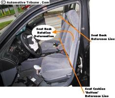
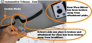
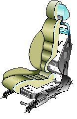
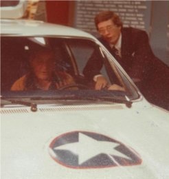
Unrestrained driver upper torso impacts steering wheel and lower extremities impacts lower dash
MATHEMATICS FOUNDATION —
Mathematics are at the core of traffic accident reconstruction. Many different equations are used to determine different aspects of an accident. Sir Isaac Newton developed three mathematical laws of motion which provide the foundation for traffic accident reconstruction.
In Newton’s first law of motion an important property of matter appears. It is known as inertia, that property of matter by which an object maintains a constant velocity in the absence of an unbalanced external force. When an automobile is suddenly stopped, the passengers obey Newton’s first law and continue in their motion with constant velocity until some external force changes their state of motion. Seat belts in a automobile can provide such an external force which is much preferred to that exerted by the windshield or dashboard. Another statement is the following: A body at rest remains at rest, and a body in motion remains in motion with constant velocity along the same straight line unless acted upon by some outside force.
A body at rest remains at rest, and a body in motion remains in motion with constant velocity along the same straight line unless acted upon by some outside force.
Newton’s second law of motion states that if a body is acted upon by an unbalanced force F, its center of mass will accelerate in the direction of the force. The acceleration, a, is proportional to the force, F, and the constant of proportionality, m, is called the mass of the body. Another statement is the following: The acceleration of a body is directly proportional to the resultant force action upon the body and acceleration is inversely proportional to the mass of the body.

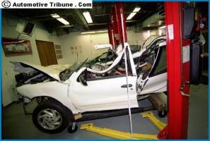
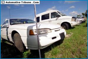
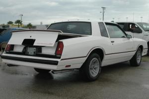
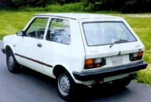
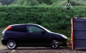
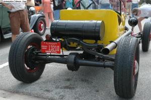
High Speed Single Car Event
Newton’s second law provides the key relationship between force and acceleration since force and acceleration are vectors and vectors have both magnitude and direction. Mass is only a magnitude, so it follows that the magnitude of force equals the magnitude of acceleration times the mass. Unification of these concepts reveals that force direction must be the same as the direction of the acceleration because mass does not have a directional property.
The second law is written F = ma where the unit of force is the newton. One newton produces an acceleration of one meter per second, per second, in a mass of one kilogram. One newton has a value of .2248 lb.
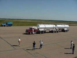
 Newton’s third law of motion states that: Action = Reaction. In this example Action (force exerted by the trailer) is equal to the reaction (force exerted on the car by the trailer).
Newton’s third law is equally valid in dealing with bodies at rest or in motion, either uniform or accelerated. The wheels of an automobile in motion push backward on the road, but the road pushes forward on the wheels with an equal force during acceleration. Another statement is the following:Whenever one body exerts a force upon a second body, the second body exerts an equal and opposite force on the first.
Whenever one body exerts a force upon a second body, the second body exerts an equal and opposite force on the first. Action = Reaction
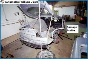
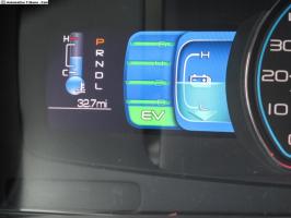
Speed Change
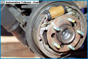
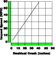
DV assumes that collision stopping force on a vehicle is a linear function of residual crush depth. Up to a certain force level, there is no permanent damage and beyond that point, permanent damage increases with increased force. Two stiffness coefficients, A and B, define the force-damage curve. Fundamental to a solution for speed change are appropriate A and B values for a specific vehicle. A and B values are derived from the collision damage sustained from known velocity changes of a vehicle into a barrier. Therefore, A and B values can be used to calculate speed change based on permanent vehicle crush (see chart).
 Vehicle tests sponsored by the National Highway Traffic Safety Administration resulted in a series of computer programs released to the public called CRASH. The last public version CRASH3 was revised and released in 1982. Several computer based accident analysis programs are available for the accident reconstructionist, each ultimately stems from this background.
A collision analysis project is defined as a series of step by step calculations. The investigator will organize the project into separate events which require solutions for specific unknowns. Normally, each event or step will consist of an equation with only one unknown. The art of collision analysis is to determine which event to solve first and then how to proceed with the next calculation to develop a unified collision sequence analysis.
Calculations from a popular AI Tools computer program help to address specific information needed in order to piece together the accident reconstruction. When properly used each calculation will help to fill in a missing piece of information.
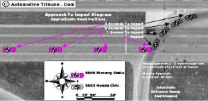
 Equation #1 Speed from Distance & Drag. Calculation of vehicle speed made from skid distance and drag factor. Measured skid distance is 120 feet and deceleration factor for the vehicle & road surface combination is .7 G. The vehicle is calculated to have been going 50 mph when the brakes were applied.
Here is a list of AI Tools calculations:
Eq Group Eq # Problem Description
Speed 1 Speed from Distance & Drag
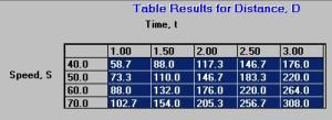
2 Constant Speed from Distance & Time
3 Speed from Drag & Time
4 Final Speed from Start Speed, Drag & Time
5 Final Speed from Start Speed, Drag & Distance
6 Start Speed from Final Speed, Drag & Time
7 Start Speed from Final Speed, Drag & Distance
Time 10 Time from Constant Speed & Distance
11 Time from Speed & Drag
12 Time from both Speeds & Drag
13 Time from Distance & Drag
Distance 20 Distance from Speed & Drag
21 Distance from Constant Speed & Time
22 Distance from Two Speeds & Drag
23 Distance from Initial Speed, Drag & Time
Acceleration 30 Drag from Speed & Distance
Factor 31 Drag from Speed & Time
32 Drag from both Speeds & Time
33 Drag from both Speeds & Distance
34 Drag from Distance & Time
35 Drag from Initial Speed, Distance & Time
36 Drag from Road Friction, Brake Efficiency & Grade
37 Drag from Horizontal Force & Weight
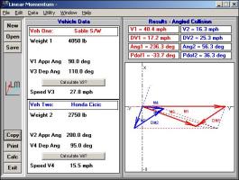
Linear 40 General Two-Dimensional Momentum
Momentum 41 Inline – V1 from V2, V3, and V4
42 Inline – Coefficient of Restitution
43 Inline – Plastic, V3 = V4
44 Inline -Elastic
Special 45 Tangent Offset
46 Radius from Chord and Mid-Ordinate
47 Critical Curve Speed
48 Combined Speed from Drag Surfaces
49 Combined Speeds
Airborne 50 Horizontal Launch and Fall Speed
51 Small Angle Speed at Launch Equation
52 General Projectile Speed Equation
Energy 60 Speed from Linear Kinetic Energy
61 Kinetic Energy from Speed and Weight
62 Force from Kinetic Energy and Distance
63 Distance from Kinetic Energy and Force
Motorcycle 70 Lateral Acceleration Factor from Speed and Radius
71 M/C Lean angle from Speed and Radius
72 Turning Radius From Speed and lateral acc
Animation 80 Final Speed from Start Speed, Drag and Time
Assist 81 Distance from Start Distance, Speed, Drag and Time
Reaction 90 Total D from P/R time, Speeds & Drag f
Times 91 Total D from Start Speed, Times & f
92 P/R Time from Speeds, Total D & f
93 P/R Time from Start Speed, Total D, f & Time
94 Start Speed from Total D, Times & Drag
95 Start Speed from Total D, Final Speed, P/R Time & f
96 Drag from Speeds, P/R Time & Total D
97 Drag from Start Speed, Total D & Times
98 Total Time from P/R Time, Speeds & f
99 Total Time from P/R Time, Brake D & Drag
Momentum
Momentum is a restatement of Newton’s laws in a form that is useful for the collision analysis or any event which involves very short periods of time. The second law for a single object would be rewritten as F Dt = m DV.
The left side of the equation is the Impulse and the right side is the Change in Momentum. This relationship is still a vector relationship. Force has the same direction as the change in momentum which has the same direction as the change in velocity. In summary:
Impulse = Change in Momentum
 If two vehicles collide, the force or impulse on one of the vehicles is equal and opposite to the force on the other. This is a consequence of Newton’s third law. Changes in momentum for both collision vehicles cancel. There is no gain or no loss of momentum during a collision. Momentum before the collision equals the momentum after the collision and because weight is proportional to mass the final equation can be rewritten as:
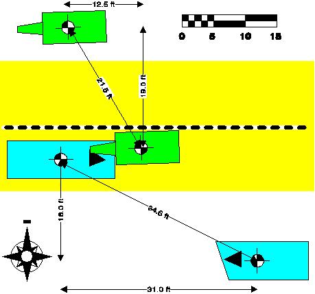
W1V1 + W2V2 = W1V3 + W2V4.
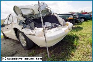
On the left is a three car collision. AI Tools Linear Momentum module below, calculates that the Chevy Lumina came into the collision at 27 mph and that the Dodge had an entry speed of 15 mph. Equation #1 was initially used to determine slide to stop, or departure, speeds for each vehicle.